jDuck hardware setup
- Connect CSI camera to Jetson Nano board
- Connect Motor Driver to Jetson Nano Board
- Connect USB-C Power Cable
- Power ON/OFF
Connect CSI camera to Jetson Nano board
To install a camera module, connect its flex ribbon cable into the camera connector (J5). Follow these steps:
- Gently lift up the the connector latch on the Jetson Nano board
- Insert the camera ribbon cable. The metal contacts should face toward the center of the developer kit.
- Gently press down on the connector latch until stops. This may require two fingers, each at one end of the latch. Do not use excessive force.
FFC Cable Direction
Set the metal side of the FFC cable into the heat-sink of the Jetson board
Connect Motor Driver to Jetson Nano Board
We use 6 pins from J6 header on the Jetson Nano to the L298N driver.
| Left Motor | Right Motor | Connection Pins |
|---|---|---|
| Pin 32 | Pin 33 | 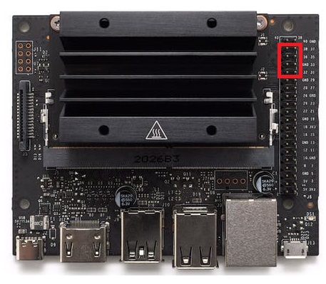 |
| Pin 36 | Pin 35 | |
| Pin 38 | Pin 37 |
Details for the electrical wiring are available at.  Electrical wiring
Motor Driver Connector
Set the small side of the ribbon cable connector into the heat-sink of the Jetson board
Connect USB-C Power Cable
Power ON/OFF
Click the power button on the power bank to turn ON jDuck.
A clear LED digital readout shows the accurate percentage of power level. No more guessing about the remaining power and when to recharge.
Double-click the power button on the power bank to turn OFF jDuck.